Recently I had to replace a 4-way switch, an electrical component that lets you turn a light on or off from three or more locations. While installing it, I thought about the binary properties of my three-switch circuit: I saw powers of two, binary logic, and binary gray code. I drew some diagrams, including a state machine. I’ll share my thoughts and diagrams with you in this article.

On/Off, 3-Way and 4-Way Switches
To control a light from one location, all you need is a simple on/off switch. The switch either closes the circuit, in which case the light goes on, or it opens the circuit, in which case the light goes off. Essentially, the switch takes two ends of a wire and connects or disconnects them. In a one-switch circuit, the position of the switch correlates with the state of the light; for example, up will mean on, and down will mean off.
To control a light from two locations, you need two 3-way switches, connected by two “traveler” wires. For example, here’s a two-switch circuit, with both 3-way switches in the down position:
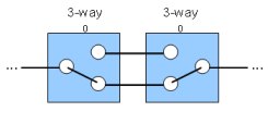
Each switch can be up or down, connecting a single wire to one of two other wires. Since there are two switches that can each be in two positions, there are 22 = 4 switch states in all.
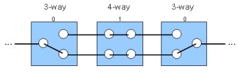
To control a light from three or more locations, you need one or more 4-way switches sandwiched between two 3-way switches, with a pair of traveler wires connecting each switch. For example, here’s a three-switch circuit, with both 3-way switches in the down position and the 4-way switch in the up position:
When the 4-way switch is in the down position, the traveler connections are crossed, inverting the state of the circuit; for example:
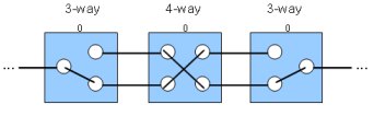
(I’m assuming arbitrarily that “up” is the direct connection and “down” is the crossed connection; I don’t know what it actually is, but it doesn’t matter.)
With three switches, there are 23 = 8 different switch states. (You can see the pattern — with n switches, there are 2n states.)
In a multiple-switch circuit, the position of an individual switch does not correlate with the state of the light — turning a switch up or down can turn the light on or off, depending on the position of the other switch(es).
A Three-Switch Circuit
Here are all eight states of a three-switch light circuit:

Here are the same states, but shown with the position of the light switches (the switches are of course separate, but I’ve drawn them together):

Of the eight states, half close the circuit and turn the light on, and half open the circuit and turn the light off.
State Machine
This state machine captures the logic of any switching sequence:

There are eight states. Each arrow represents the change of position of one switch — to up or down. From each state you can go directly to three other states. You can go indirectly to any other state by traversing a path through the diagram. The light toggles from off to on or from on to off with each change of switch position.
Gray Code
If each switch is viewed as a bit — I’ve labeled up as ‘1’ and down as ‘0’, by convention — then there are eight binary values: 000, 001, 010, 011, 100, 101, 110, 111. As listed, that is the counting order for the binary integers zero through seven. In this order, multiple bits can change between two adjacent numbers; for example, two bits change from 001 to 010. But in a light circuit, no toggling sequence of the eight states can result in binary counting order, because only one switch can change at a time (I’m not counting two or three people toggling switches at the same time!).
This is where gray code comes in. A gray code is an ordering of binary numbers such that only one bit changes between adjacent numbers. For example, a three-bit gray code — known as the binary reflected gray code — is 000, 001, 011, 010, 110, 111, 101, 100. (You’ll note that that’s the order in which I listed the switch states in the diagrams above). There are many possible three-bit gray codes, each represented by a unique traversal of all eight states in the state diagram.

I have 3 ceiling lights connected on a 3 switch circuit, one being a 4 way and two 3 way’s. I want to make one 3 way switch seperate from the others for a fan with a remote control and receiver. How can I do this my self without rewireing all.
Thanks
@John,
Sorry I can’t help — I’m not an electrician.
Nice post; using the gray code I see a checkerboard K-map. With Reed-Muller logic and n switches S_n, light L status is:
S_1 ^ S_2 ^ … ^ S_n = L
@Jason,
I hadn’t seen the Reed-Muller connection, but I see it now. That’s a good way to look at it. (It’s been a long time since I thought about Reed-Muller; this Clive Maxfield article brought me up to speed.) The XORs tell us that the light is on only when there are an odd number of switches in the up (1) position.
Thanks for the comment.
Superb. I have been planning to fix the 3- and 4-way switch system in my brother’s house, which was miswired when the house was built nearly 50 years ago. I thought I would simply look for anomalies with a little switch-flipping and then fix it. Didn’t happen; I was more confused than when I started. (It’s a 4-switch system) So I set about generating a truth table for the 16 states, but even with K-maps, couldn’t see a pattern that hinted which switch was miswired.
Then today, it hit me: it’s a Gray Code setup – any time ANY switch changes state, the light should change state. I rearranged my truth table via Gray Code and watched the light turn off and on, off and on – until it didn’t. I went straight to the miswired switch. Then I googled up your site, and the circle closes. Thanks.
@James,
Tell me more about how the system was initially miswired (what was happening, or not happening?). How did you correlate your diagram to the actual switches?
It sounds like we need to add this to the electricians’ training manual 🙂 .